Home > Products > SST–2 Freeze Protection Thermostats
Features & Benefits
- Automatic freeze protection
- 40°F (4.4°C) set point
- Automatic supply voltage selection
- Two-pole contactor switches up to 30 AMP heater loads
- Alarm relay with isolated contact
- Integral 30 mA GFEP
- C-UL-US listed
- Simple to install and operate
- Minimum energy costs


Description
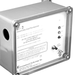
The C-UL-US listed SST–2 Freeze Protection Thermostats replace electromechanical thermostats in cost-sensitive applications requiring ground fault equipment protection (GFEP). The SST–2 is listed by Underwriters Laboratories to Standard UL 873 for Temperature- Indicating and -Regulating Equipment.
The SST–2 operates heaters at temperatures below 40°F (4.4°C) and turns them off above 42°F (5.5°C). The external temperature sensor (supplied) is a NEC Class 2 device rated for wet locations.
The SST–2 features a built-in 30 mA GFEP that is digitally filtered to minimize false tripping. A ground fault must be manually reset with the TEST/RESET switch before heater operation can be resumed. The GFEP function is automatically tested along with the heaters whenever power is applied and once every 24 hours thereafter for additional safety.
The SST–2 includes an alarm relay with an isolated SPDT 1 AMP contact. The alarm relay is reverse acting and is normally closed unless there is a ground fault condition, GFEP circuitry fails a test, or when there is a bad temperature sensor.
The SST–2 Freeze Protection Thermostats operate from automatically selected operating voltages of 120, 208, 240 or 277 volts, single-phase. They control heater loads of up to 30 amps while consuming less than 2 watts when idling. The temperature sensor is an NEC Class 2 device that can be located up to 2,000' (610 m) away from the SST. They operate in non-hazardous environments in a temperature range extending from −40° to 131°F (−40° to 55°C). The rugged non-metallic enclosure is appropriate for installation in indoor or outdoor locations suitable for NEMA 4x applications.
For complete information describing its application, installation and features, please contact Customer Service or check on the web at www.networketi.com.
Specifications
| General | |
|---|---|
| Area of use | Nonhazardous locations |
| Approvals |  |
| Enclosure | |
|---|---|
| Protection | NEMA 4X |
| Cover attachment | Polycarbonate cover, machine screws |
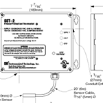
| Entries | 1 × 3/4" entry (bottom right) for NEC Class 2 connections 3 × 1-1/16" entries (bottom left and left) for supply and load power |
| Material | Polycarbonate |
| Mounting | Wall mounted |
| Front Panel Interface | |
|---|---|
| Status indicator | SUPPLY (green) power applied SUPPLY (green, flashing) bad thermistor HEAT (yellow) call for heat GFEP (red) ground fault condition GFEP (red, flashing) failed GFEP (red, flashing, rapid) GFEP test in progress |
| Remote Interface (SST–2 only) | |
|---|---|
| Alarm relay | Isolated SPDT 1 AMP Class 2 contact |
| Summary alarms | No Power Ground Fault Condition GFEP function test failure Bad or missing Thermistor |
| Control | |
|---|---|
| Supply voltage | 120, 208, 240 or 277 volts, single phase (automatically selected) |
| Contact type | Two Form A DPST |
| Maximum ratings | Voltage: 277 VAC Current: 30 amps |
| High Limit Thermostat | |
|---|---|
| Set point | 40°F (4.4°C) |
| Dead band | 2°F (1°C) |
| Sensor type | Thermistor network |
| Circuit type | NEC Class 2 |
| Lead length | Up to 2,000' (610m) using 12 AWG 2-wire jacketed cable Up to 500' (152m) using 18 AWG 2-wire jacketed cable |
| Ground Fault Equipment Protection (GFEP) | |
|---|---|
| Set point | 30 mA |
| Automatic self-test | Mode A: Verifies GFEP function before contactors operate Mode B: Verifies GFEP and heaters every 24 hours |
| Manual test/reset | TEST/RESET switch of front panel |
| Environmental |
|
|---|---|
| Operating temperature | −40°F to 130°F (−40°C to 55 °C) |
| Storage temperature | −67°F to 167 °F (−55°C to 75 °C) |
In this section:


