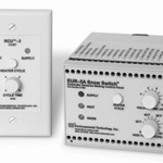
Home > Products > EUR–5A Snow Switch® Panel Moutned Control
Features & Benefits
- Multiple sensor capability
- Remote control included
- Building and energy management computer interface
- Adjustable heater hold-on timer
- Local and remote heater toggle switches
- High ambient temperature limit
- NEC Class II operation
- 35 MM DIN rail mounting
- Energy efficient automatic operation
- Wide range of applications
- Electric panel location


Description
The EUR–5A brings the performance, economy and energy efficiency of the industry leading APS–3B to a wide range of commercial snow melting applications requiring electrical panel location. A rich assortment of features optimize EUR–5A performance for its intended applications and environment.
The EUR–5A interfaces multiple sensors from the CIT–1, GIT–1, SIT–6E family for flexibility in a wide range of pavement, gutter and downspout deicing applications. This feature is essential for large systems employing common heater switching.
Continuing heater operation after snow stops is often necessary to ensure complete melting. The EUR–5A provides an adjustable 10 hour hold-on timer for this purpose. Blowing, drifting and tracked snow sometimes occur without contacting a sensor. In this case, heaters can be manually toggled on for the hold-on time.
The EUR–5A includes an RCU–3 Remote Control to be placed at a location convenient for personnel capable of observing melting. It provides status indicators, a calibrated hold-on timer adjustment and a heater toggle switch. So, melting can be manually initiated should the need arise.
The EUR–5A interfaces a low voltage push-button switch that toggles the heaters for the hold-on time. When mounted on the front panel of the electrical enclosure, this feature eliminates the need to open the panel which promotes safety.
Energy and building management computers are becoming increasingly common. The EUR–5A accommodates this trend through an interface designed for this purpose. In addition to system status information, the interface permits remote overriding automatic operation to turn the heaters on or off upon command.
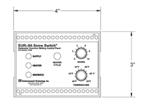
The 40°F to 90°F (4°C to 32°C) adjustable high temperature limit protects heaters, asphalt, pavement and other sensitive materials from damage due to excessive temperature while allowing heater testing during the summer months. At temperatures above the limit setting, toggled heaters operate for 30 seconds. Thereafter, the heater cannot be energized for two minutes. The standard temperature sensor is included. Options include pavement and aerial housings.
The EUR–5A and its sensors are 24 VAC NEC class 2 devices for easy installation and safety. The EUR–5A allows for 35 MM DIN rail mounting in electrical enclosures. The isolated SPDT 1 AMP 24 VAC relay contact controls the heater control contactors. A 120:24 VAC control transformer is included.
Specifications
| Front Panel Interface | |
|---|---|
| Status Indicators | Supply (green LED) Snow/Ice (yellow LED) Heat (yellow LED) |
| Heat Toggle Switch | At and above the temperature limit Below the temperature limit |
| Hold-on Time Adjustment | 0 to 10 hours |
| Temperature Limit Adjustment | 40°F to 90°F (4°C to 32°C) |
| Sensor Interfaces |
|
|---|---|
| Moisture/Temperature Sensors | Up to six can be used simultaneously Members of the CIT–1/GIT–1/SIT–6E family in any combination Locate up to 2,000' (609.6m) from EUR–5A |
| Ambient Temperature Sensor | ETI Part Number 19272 with Thermistor Temperature included Locate up to 2,000' (609.6m) from EUR–5A |
| Remote Interfaces | |
|---|---|
| RCU–3 Remote Control Unit | |
User interface: |
Hold-time adjustment SUPPLY and HEAT LED indicators 2, 4, 6 or 8 hour hold-on time adjustment |
Installation: |
Mounts in a single gang wall box up to 500' (152.4m) Non-polar electrical connections using 2 wires |
| Building/Energy Management Computers | |
Input interface: |
Floating switch contact rated a 5 VDC at 10 mA |
Functions: |
OVERRIDE_ON: Operates heaters continuously independent of environmental
conditions. Operation is inhibited at temperatures above the high temperature limit. OVERRIDE_OFF: Inhibits heater operation. |
Output Interface: |
Normally open floating dry circuit Form A (SPST) switch contacts rated for 5 VDC at 10 mA |
Status Indicators: |
SUPPLY (green LED): EUR–5A power present SNOW/ICE (yellow LED): At least one sensor detects icing conditions HEAT (yellow LED): EUR–5A is calling for heater operation |
| Electric Panel | Normally open Form A (SPST) push button low current switch Operation toggles heaters on for the hold-on time or off |
| Heater Control Relay | |
|---|---|
| SPDT relay contact rated for 1 AMP 24 volt pilot duty service | |
| Operates while the EUR–5A calls for heat | |
| Supply Voltage | |
|---|---|
| Use ETI Order Number 14257 Control Transformer (included) | |
| NEC Class 2 | |
| 21 to 28 VAC | |
| 2 VA maximum | |
| Environmental |
|
|---|---|
| Operating temperature | −40°F to 140°F (−40°C to 60 °C) |
| Storage temperature | −67°F to 167 °F (−55°C to 75 °C) |
| Mechanical |
|
|---|---|
| Housing | NEMA 1 |
| Mounting | On 35 MM DIN rail. DIN rail interface can be removed for conventional mounting. |
| Dimensions | 4" wise by 4 7/8" deep by 3" high |
In this section:


