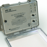
Home > Products > APS–4C Snow Switch® Control Panel with integral gfep
Features & Benefits
- Automatic snow/ice melting control
- Satellite contactor interface for larger system
- Energy management computer (EMC) interface
- Accommodates MI, constant wattage and self-limiting heaters
- Multiple sensor capability
- Advanced patented and patent pending ground fault protection
- Heater hold-on and test capability
- C-UL-US
- Simple to install and operate
- Low energy costs
- Minimum energy costs


Description
The APS–4C Snow Switch when used with one, or more, compatible sensors automatically controls snow/ice melting heaters for minimum energy costs. Applications include pavement, sidewalk, loading dock, roof, gutter and down spout snow/ice melting in commercial and industrial environments. The APS–4C is interchangeable with the earlier APS–4.
The adjustable hold-on timer continues heater operation for up to 10 hours after snow stops to ensure complete melting. The optional RCU–4 Remote Control Unit can be located where system operation can be conveniently observed. It duplicates many of the APS–4C front panel functions.
The APS–4C provides advanced patented and patent pending ground fault equipment protection (GFEP) as required by the USA and Canadian National Electric Codes. The GFEP automatically tests itself every time the heater contactors operate and once every 24 hours. The trip current can be set at 60 or 120 ma via a DIP an internal switch or retained at the 30 ma default value. As an aid to troubleshooting heater ground faults, the APS–4C provides an output that can indicate the ground current on a service person’s portable DVM.
The calibrated 40°F to 90°F (4°C to 32 °C) high limit thermostat prevents excessive temperatures when using constant wattage and MI heaters. It also permits safe testing at outdoor temperatures too high for continuous heater operation. The temperature sensor is included.
The APS–4C provides a complete interface for use in environments supervised by an energy management computer (EMC). This feature can also be used for general purpose remote control and annunciation.
All sensor and communications wiring is NEC Class 2. This simplifies installation while enhancing fire and shock safety. The APS–4C can interface up to six sensors from the CIT–1 product family. More sensors provides superior performance by better matching the controller to site performance requirements.
Specifications
| General | |
|---|---|
| Area of use | Nonhazardous locations |
| Approvals |  |
| Enclosure | |
|---|---|
| Protection | NEMA 3R |
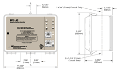
| Cover attachment | Hinged polycarbonate cover, lockable |
| Entries | 1 × 1-1/16" entry (top) for NEC Class 2 connections 2 × 1-11/16" entries (bottom) for supply and load power, except 277 VAC single phase 2 × 1-1/16" entries (bottom) for supply and load power, 277 VAC single phase only |
| Material | Polycarbonate |
| Mounting | Wall mounted |
| Control |
|
|---|---|
| Supply | ETI PN 22472: 208-240 VAC, 35 VA, 3-phase 50/60 Hz ETI PN 22473: 277 VAC, 45 VA, single phase 50/60 Hz ETI PN 22475: 277/480 VAC, 45 VA, 3-phase 50/60 Hz ETI PN 22476: 600 VAC, 50 VA, 3-phase 50/60 Hz |
| Load | ETI PN 22472: 208-240 VAC, 50 amp max. resistive ETI PN 22473: 277 VAC, 40 amp max. resistive ETI PN 22475: 277/480 VAC, 50 amp max. resistive ETI PN 22476: 600 VAC, 50 amp max. resistive |
| Contact type | 3 Form A |
| Maximum Ratings | Voltage: 600 VAC Current: 50 amps |
| Heater hold-on timer | 0 to 10 hours; actuated by snow stopping or toggle switch |
| System test | Switch toggles the heater contact on and off. If temperature exceeds high limit, heater cycles to prevent damage. |
| Ground Fault Equipment Protection (GFEP) | |
|---|---|
| Set point | 30 mA (default); 60 mA and 120 mA selectable by DIP switch |
| Automatic self-test | Mode A: Verifies GFEP function before contactors operate Mode B: Verifies GFEP and heaters every 24 hours |
| Manual test/reset | Toggle switch provided for this function |
| Maintenance facility | DC output proportional to ground current provided for troubleshooting the heater system |
| Snow/Ice Sensors | |
|---|---|
| Sensor type | Up to 6 sensor from the CIT–1 product family |
| Circuit type | NEC Class 2 |
| Lead length | Up to 500' (152m) using 18 AWG 3-wire jacketed cable Up to 2,000' (609m) using 12 AWG 3-wire jacketed cable |
| High Limit Thermostat | |
|---|---|
| Adjustment range | 40°F to 90°F (4°C to 32°C) |
| Dead band | 1°F (0.6°C) |
| Sensor type | Thermistor network |
| Circuit type | NEC Class 2 |
| Lead length | Up to 500' (152m) using 18 AWG 2-wire jacketed cable Up to 1,000' (504m) using 12 AWG 2-wire jacketed cable |
| Energy Management Computer (EMC) Interface | |
|---|---|
| Inputs | OVERRIDE ON (10 ma dry switch contact) OVERRIDE OFF (10 ma dry switch contact) |
| Outputs | SUPPLY (10 ma dry switch contact) SNOW (10 ma dry switch contact) HEAT (10 ma dry switch contact) HIGH TEMP (10 ma dry switch contact) ALARM (10 ma dry switch contact) |
| Environmental |
|
|---|---|
| Operating temperature | −40°F to 160°F (−40°C to 71°C) |
| Storage temperature | −50°F to 180°F (−45°C to 82°C) |
In this section:


